
Metallic strain gauges are electrical resistors on a carrier material. The resistance value is defined by the length and cross section of the conductive path. The carrier material primarily consists of a base body with a weakened surface, which is subjected to deformation due to the pressure: the membrane.
The strain gauges are firmly connected to the membrane and express the mechanical deformation as a change in their resistance value. During expansion, the conductive path protracts and the cross section tapers – the electrical resistance increases. During compression, the cross section of the conductive path increases and the length diminishes – the resistance decreases.
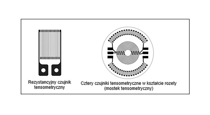
Fig. 1: Strain gauges
There are usually 4 strain gauges on the membrane, which are connected to form a Wheatstone bridge (Fig. 1). They work against each other, i.e. during deformation of the membrane, the outer strain gauges are compressed and the inner ones are expanded. Thanks to the bridge circuit, the output signal is four times stronger than it would be with a single strain gauge.

Fig. 2: Wheatstone bridge
The temperature-related resistance changes are also offset. The bridge voltage is Ud= 0 V at the resting position of the membrane. In the event of a temperature increase at the membrane, all resistors are heated evenly. The ratio of the bridge is still balanced – the bridge voltage remains 0 V.
If the membrane is pressurized, the internal resistors R1 and R3 expand – their resistance increases. At the same time, the external resistors R2 and R4 are compressed – the resistance decreases. The ratio of the measuring bridge is changed in both directions. The voltage Ud increases.
Fig. 3: Schematic diagram of a membrane with strain gauges